
Installing and Setting Up the Dual Motion Plate
The Dual Motion Plate combines a force plate and a pressure (balance) plate on each side. This guide covers connecting the plates, calibration, component detection, and troubleshooting.
Applies to:
- Motion Catalyst and Swing Catalyst.
Installation
For physical installation, see the attached PDF guides:
- See the Install Guide PDF for preparing your room for the installation.
- See the Start Guide PDF for setting up the Motion Plate for use.
In addition to the start guide, familiarize yourself with the calibration test below.
Requirements
- Bertec CDM driver installed.
- MeasureX driver installed. See How to install Balance Plate 3S for install details.
- Dual Motion Plate hardware.
The software installs the drivers for the force plates and pressure plates automatically, except the pressure plate calibration file. You should not need to install the drivers manually.
Connecting the plates
A dual plate setup has 4 cables in total, of two connector types:
| Cables | Connector | Connects to |
|---|---|---|
| 2 | USB Mini B | The two balance plates |
| 2 | USB-B (larger connector than USB Mini B) | The two force plates |
A powered USB hub is useful if you want to avoid using all the available USB ports on the computer.
Connection procedure
- Connect the two USB Mini B cables to the two balance plates.
- Connect the two USB-B cables to the two force plates.
- Connect all 4 cables from the plates to the computer.
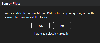
If the plate configuration is not detected automatically, disconnect and reconnect some of the cables and restart the software.
Click Yes to proceed.
Once the software has identified all the plates that make up a Dual Motion Plate, calibrate the plate:
- Make sure no one is standing on the plate and that the plates are clear of any surrounding turf or equipment.
- Click Calibrate.
This zeroes the force plate. If calibration fails, see the troubleshooting section.
Component detection
The software needs to know which plate is in front, or on the right. Click Detect and follow the on-screen instructions.
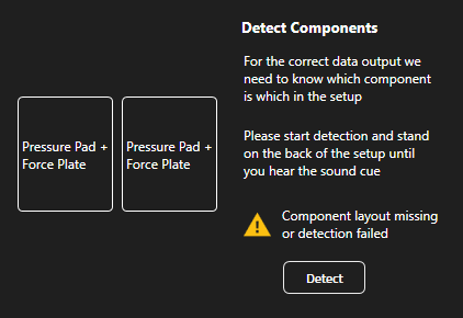
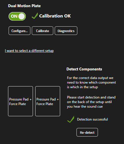
Calibration test
There are two types of calibration:
- The zero level for the force plate.
- The calibration file for the pressure (balance) plate.
This test checks the force plate part of the Motion Plate to verify that it is installed correctly. A good calibration is important for accurate data.
Calibrate and test the calibration before every session of a series of recordings.
- Click Calibrate in Settings → Sensor Plates.
- Click Configure next to it, then click Play to preview live force and pressure data.
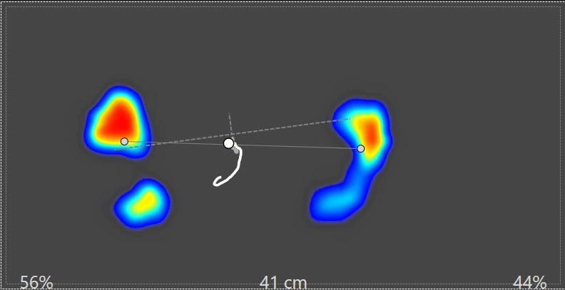
- Press on one corner of the plate with a club shaft or your heel. Verify that the pressure data (colored heat map) aligns with the force data (total CoP circle).
- If they do not align, one or more plates may need to be rotated. See How to change rotation .
- Start a session, then capture a recording with no one on the plate. Open the recording and verify the force readings are within 10 Newtons of zero.
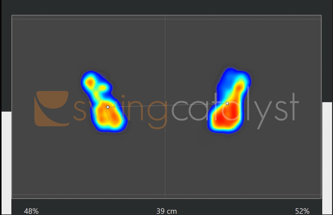
Example of the pressure dot aligning with the Center of Pressure dot:

Pressure (stance) data should read from toe to heel. The left foot should appear on the left plate (where the “swing” part of the Swing Catalyst logo is), and the right foot on the right plate. If it does not, rotate the pressure data 180 degrees.
Troubleshooting
Pressure and force data are not aligned, or calibration fails
If the CoP dot does not match the pressure dot, the plate is probably not level, or something is pressing against it and blocking its free movement.
- Click Calibrate once more, then repeat the calibration test.
- If it is still off, readjust the leveling foot of the force plate while pressing down on the opposite corner. First shorten it, then extend it to the point where it touches the floor and you feel a little resistance.
- Confirm all four feet are in solid contact with the floor by pressing down on the corners.
- Make sure there is no turf or similar pressing against the plate.
- Repeat the calibration test.
Pressure data (footprint) is missing on one plate
- Check the connections to each pressure plate. Disconnect the plates and reconnect them.
- Restart the software.
- Verify the software recognizes both plates. Under Settings → Sensor Plates → Configure → Sensor Info there should be two serial numbers, for example 1230_1231. If only one number is listed, the second plate is probably not being recognized.
- Check the Windows Device Manager. There should be two entries under Ports (COM & LPT) called Sensor Edge MeasureX Pressure Controller, each followed by a COM port number. If you do not see them, this can point to a physical connection problem.
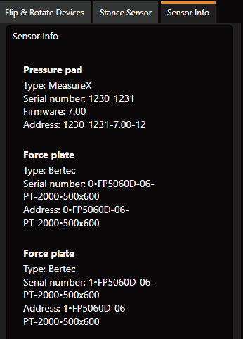
Examples of improper configuration
The examples below show incorrect configurations. Use them to recognize and troubleshoot these kinds of problems.
Pressure data is upside down
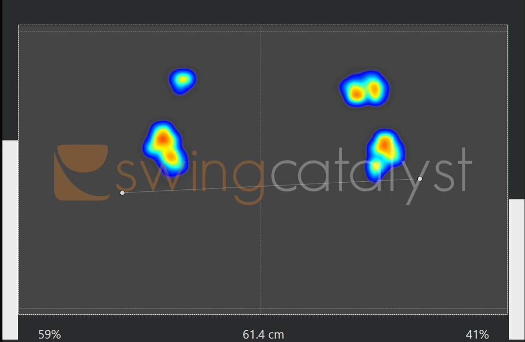
You can detect this configuration by standing on the plates and leaning forward or backward. If the CoP moves opposite to the pressure, either the force data or the pressure data needs to be rotated 180 degrees.
Pressure is upside down and force has the wrong rotation
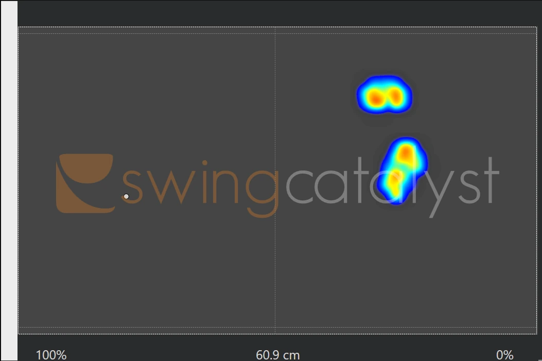
Following the logic from the calibration test above, several things are wrong in this example:
- The footprint (pressure data, also called stance data in the Swing Catalyst settings) is upside down.
- The CoP dot (the white dot next to the “S” in the Swing Catalyst logo in the background) is not aligned with the footprint.
- The CoP dot is not on the same plate as the footprint.
To fix this, first rotate the pressure (stance) data so the left foot appears on the left side, then rotate the force data until it matches the footprint.
For dual plates, apply the calibration test logic to each individual plate.
The wrong plate was stepped on during the dual plate detection phase
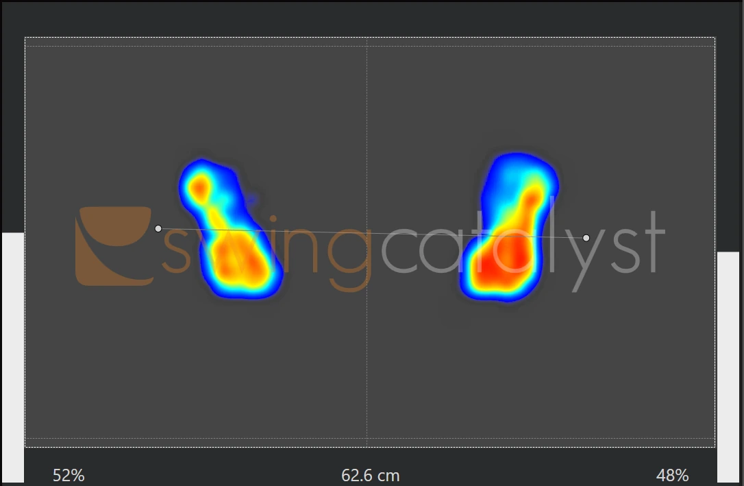
In this example the wrong plate was stepped on during the component detection phase. The pressure and force data do not align, and the CoP dots are outside the footprints, which they normally should not be.
To fix this, run component detection again and step on the plate the software highlights (the blinking plate). The data should then look like the screenshot below.
Here is the same data as above, but with the correct plate detected:
Pressure data looks correct but CoP is wrong
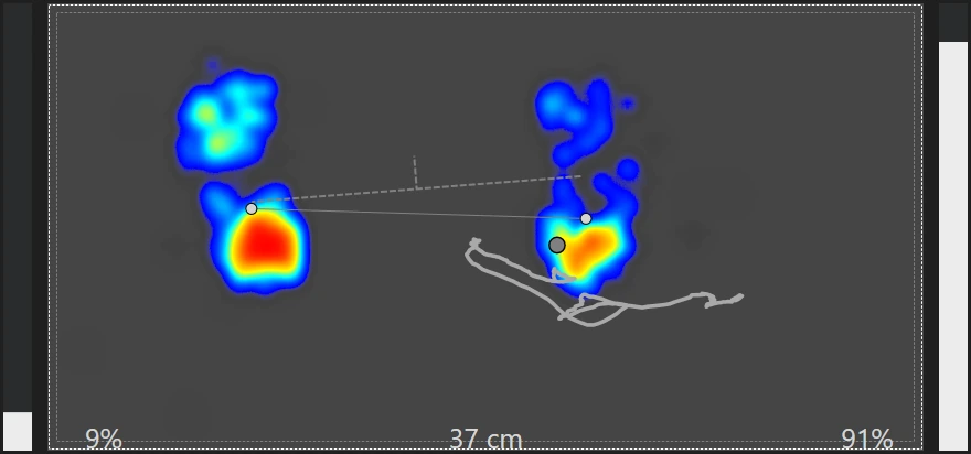
This example is from a single Motion Plate where the force data rotation is 180 degrees wrong. You can tell because the pressure data has the correct orientation (heels are down towards the bottom of the screen) while the CoP does not match.
To fix problems like this, follow the calibration test above. For dual plates, do it for each plate.
How to change rotation
Instead of physically rotating plates, you can rotate the data in software.
- Go to Settings → Sensor Plates and click Configure.
- In the Sensor Plates settings, select the Flip & Rotate Devices tab.
- To rotate pressure data, click Rotate Stance Data.
- To rotate force data, click Rotate Force Data.
The troubleshooting pictures above illustrate wrong configurations that these controls correct.
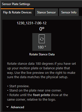
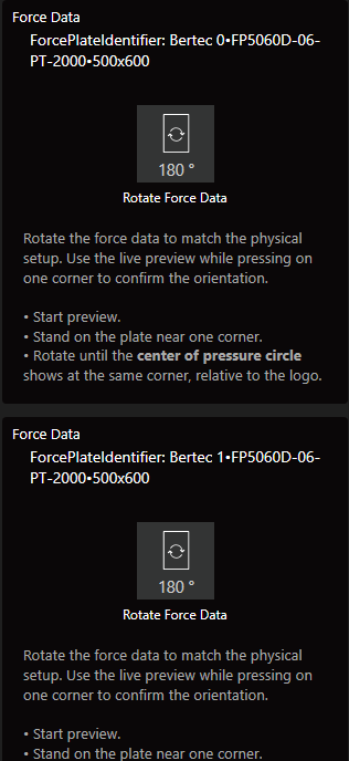
For dual plate setups the list shows two Force Data entries. Make sure to rotate both force plates in software.
Good data vs bad data
This is an example of good data. There is very little noise, and nothing indicates that something is blocking the movement of the plate.
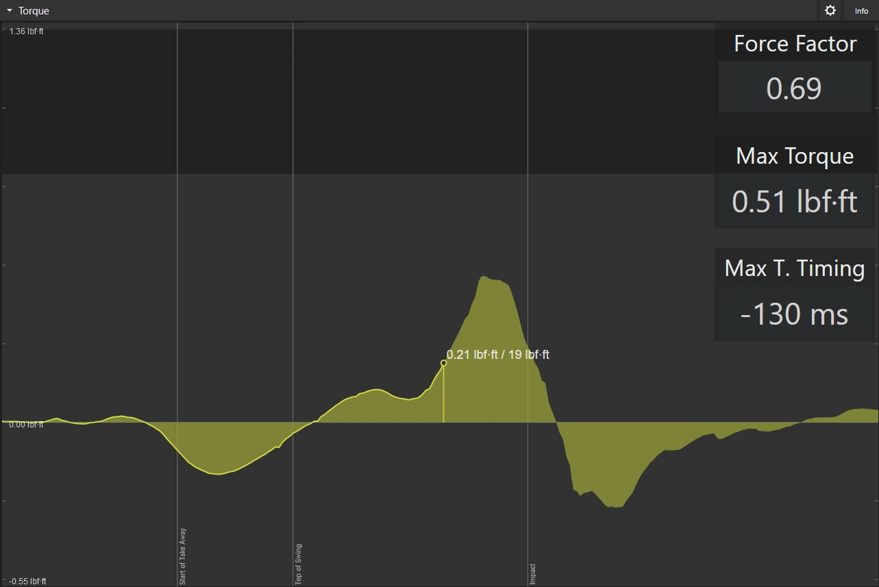
If your data is noisy, or the readings on the graphs are very low, noise from power supplies or bad grounding can be the cause. For more details, see the Force Plate technical troubleshooting guide .