
Force Plates for Baseball Pitching
Force plates embedded in a pitching mound measure the delivery from the rubber and from the landing foot. The supported layout uses three plates, and the Bertec FP9090 and FP9090-15 plates are supported. Your plate supplier’s drawings give the exact models, sizes and pit dimensions for your installation.
This is an installed setup: the plates are built into the mound, and the mound is built around them.
The three-plate layout
This setup uses three plates.
- One plate at the rubber, where the pitcher starts. It sits level.
- Two plates at the landing area, side by side with a small gap between them. They sit on the slope of the mound.
The two landing plates sit forward of the rubber plate, where the stride lands, with a gap between them and the rubber. Exact spacing and pit sizes come from the plate maker’s drawings for your specific models, which is what the pits must be cut to.
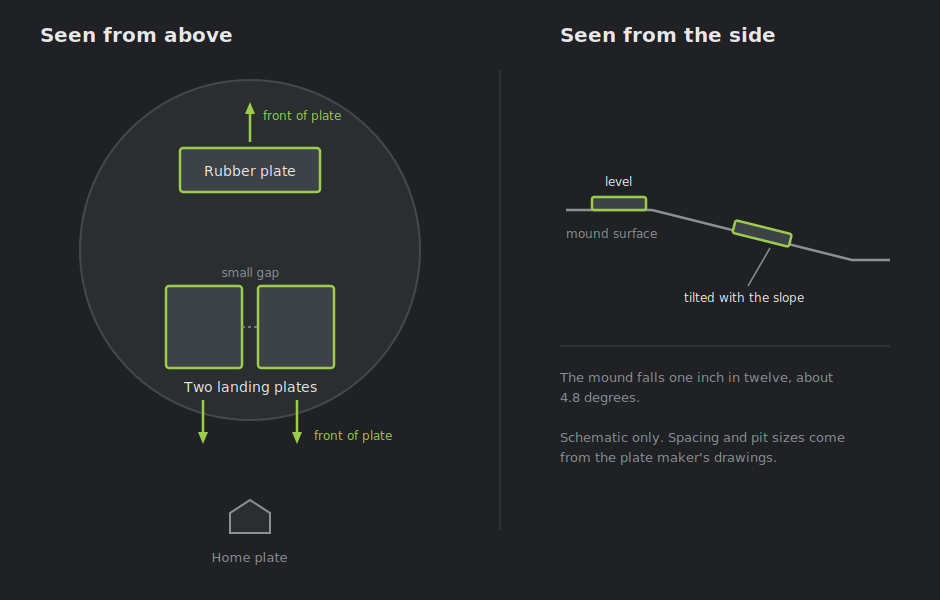
The drawing is schematic. It shows which plate goes where and which way each one faces, not the distances.
Why the mound slope matters
A regulation mound falls one inch for every twelve, about 4.8 degrees. The landing plates are set into that slope, so they are tilted.
A tilted plate reports some of the pitcher’s weight as a sideways force, because “down” for the plate is not “down” for the world. The software corrects for this using the known tilt, so the forces you read are the real ones.
What matters for your installation is that the slope the plates are actually set at matches the slope the software is configured for. If the mound is rebuilt or resurfaced and the slope changes, tell us, because the correction has to change with it.
Layout and orientation
The plates sit in pits cut for them, flush with the surface. This is construction work, planned with the plate drawings before the mound is built.
The layout is fixed by the mound, not by where you choose to stand. Plate positions follow the rubber and the landing area.
Orientation matters. The rubber plate faces away from home plate, and the landing plates face towards it. Getting this wrong flips the sign of the forces.
What you can measure
All three plates stream together. You get force from the rubber and from the landing foot as one synchronized picture of the delivery.
You get center of pressure on each plate, and combined across all three. You also get force vectors on each plate, and the share of load carried by the rubber plate against the two landing plates.
Captures use a manual trigger. You start the recording rather than the software detecting the pitch.
Planning an installation
Cut the pits to the plate maker’s drawings. The software configuration then has to match what was built: which plate is where, which way each faces, and what the slope is.
Talk to us before the mound is built rather than after. The measurements come from Bertec’s drawings for the specific plate models, and a pit cut to the wrong size is expensive to correct.